Page 1 of 1
Crank Case Ventilation Explained
Posted: Mon Jul 21, 2014 11:47 pm
by 2.5TYPE44
Here is an awesome in depth explanation on crank case ventilation, the different types, and how critical it is for forced induction motors. There is a ton of good info if you have the time to read through.
http://www.shophemi.com/images/media/p-2273-arrington_ccv_bible.pdf
Re: Crank Case Ventilation Explained
Posted: Tue Jul 22, 2014 6:44 am
by DE80q
Started reading, good info! I save to my computer to finish reading when I wake up. Thanks for finding this.
Re: Crank Case Ventilation Explained
Posted: Tue Jul 22, 2014 11:38 am
by Mcstiff
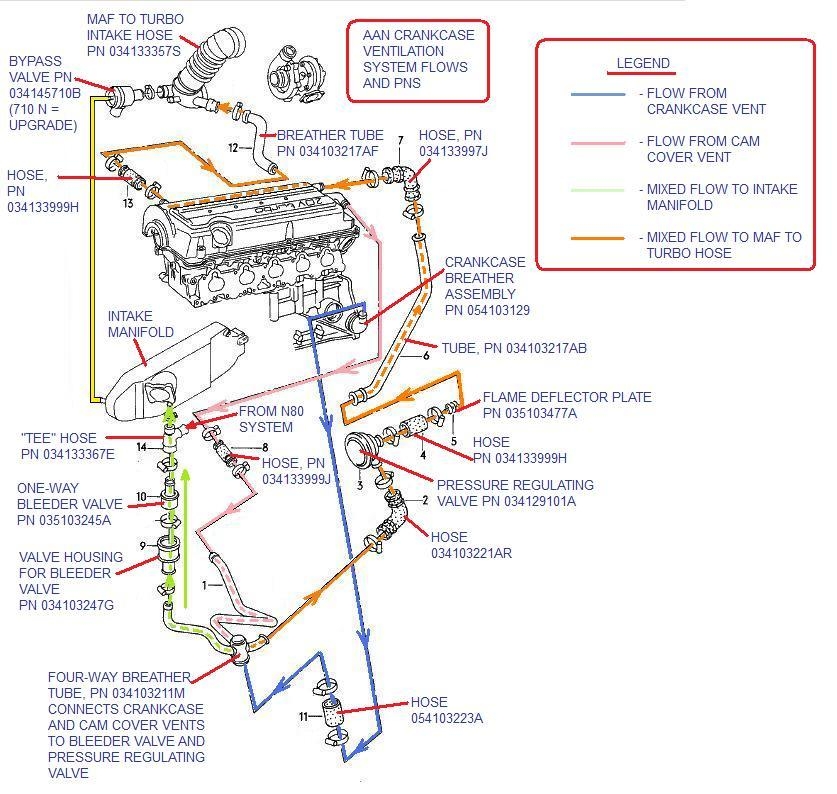
Yeah, it's good reading. It seems that #5 is the basic setup that most are running but with the suggestion of large ID hose. We've had discussions about venting from the VC only on the ur20vt to limit the blow-hole effect.
Re: Crank Case Ventilation Explained
Posted: Fri Jul 25, 2014 10:38 pm
by roortube
Good read indeed. I've run the 034 catch can kit on my Urs for years, and it worked well when the engine was stock or close to it. Recently I've had some pretty good oil leaks to deal with and it's had me considering my system. This tells me 2 provent cans with big lines to TIP and no PCV valve...sound good? Both engine side lines to valve cover, or one to cover and one to port on th email block?
Re: Crank Case Ventilation Explained
Posted: Sun Jul 27, 2014 5:37 pm
by morris400
How big of a issue would it cause if i reduced the vent on the valve cover for the pcv from 1/2in to 5/16th ? Would it cause more pressure and blow seals? Or would it be ok?
Re: Crank Case Ventilation Explained
Posted: Sun Jul 27, 2014 6:35 pm
by Mcstiff
morris400 wrote:How big of a issue would it cause if i reduced the vent on the valve cover for the pcv from 1/2in to 5/16th ? Would it cause more pressure and blow seals? Or would it be ok?
Why would you want to reduce the ID?
Re: Crank Case Ventilation Explained
Posted: Sun Jul 27, 2014 7:30 pm
by morris400
Im installing a 7a VC on the urs4 and the machine shop drilled the hole 5/16th in the 7a VC . Its not by choice byt just wondering if it will be ok or not?
Re: Crank Case Ventilation Explained
Posted: Sun Jul 27, 2014 7:56 pm
by Mcstiff
morris400 wrote:Im installing a 7a VC on the urs4 and the machine shop drilled the hole 5/16th in the 7a VC . Its not by choice byt just wondering if it will be ok or not?
So here's the thing, are you planning on installing a solid tube in the 7a VC?
If not, I'd be worried about connecting the back of the 7a vc to the PCV and what would happen when oil splashes into the tube during acceleration.
I believe most running 7a VCs simply run a tube to the inlet and bypass the VC.
Re: Crank Case Ventilation Explained
Posted: Sun Jul 27, 2014 8:12 pm
by Wheeljack
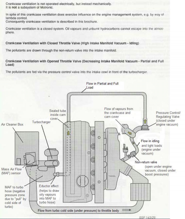
To mimic the aan setup you need both the 'sealed tube' equivalent (this is run externally on the 3B) AND the valve cover vent. The diagram above doesn't show it but there are two ports on the back of the aan cover.
Baffling is helpful as there is not as much vertical height in the 7A cover
..
Re: Crank Case Ventilation Explained
Posted: Sun Jul 27, 2014 8:40 pm
by morris400
The sealed tube i have that figured out. Im gonna run a external one just like the 3b. The oil being splashed into the vent i can work with that. My worrie now is that the hole that was drilled for the VC vent is too small and will cause an increase in pressure. is there a big issue with reducing the vent size on the valve cover ?
Re: Crank Case Ventilation Explained
Posted: Sun Jul 27, 2014 11:28 pm
by PRY4SNO
AFAIRemeber, reducing diameter increases pressure & decreases flow.