Page 1 of 1
7A harness dissection, VEMS prep
Posted: Wed Mar 23, 2016 9:58 am
by nmerrill
Folks, in preparation for an impending VEMS install for my 2.6L 20V NA Vanagon engine, I picked up a 7A harness to dissect.
I've identified almost all the wires in the harness, but have a few known unknowns...
First are two single connectors with small rubber boots that come off right by the throttle switch connector:

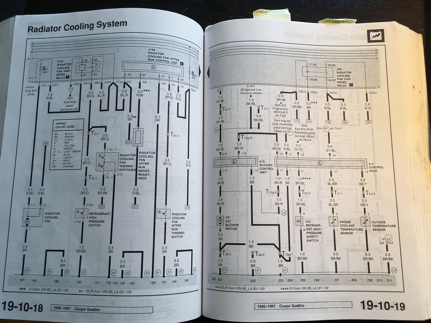
I saw something that had me thinking these were for an after-run sensor, but the 7a didn't have an after-run pump, did it? Or was it for after-run radiator fan?
Also, I can't figure out these two, which peel off right near the end of the harness, and were coated with grime, if that is a clue.
One is a t5, with only 2 contacts used, the other t3

Anyone have a clue?
Re: 7A harness dissection, VEMS prep
Posted: Wed Mar 23, 2016 11:11 am
by A1QSHIP
Can you provide the colors of the wires in question? Those plugs should have numbers corresponding to the wire location in the plug. The 7a did not have an after run pump for coolant but did have after run function for the engine cooling fan.
Re: 7A harness dissection, VEMS prep
Posted: Wed Mar 23, 2016 11:31 am
by nmerrill
The single contact connectors by the throttle switch - one is Br/green, don't have note on the other one in hand.
The T5 connector, with only two contacts wired, are Bk/Bl + Bk/Bl (two wires joined at contact), and Bl/red
The T3 connector next to the T5 above is Bk/Bl (which goes to the T5 above), Br, Br/red
Thanks
Re: 7A harness dissection, VEMS prep
Posted: Wed Mar 23, 2016 11:37 am
by nmerrill
Another thing I'm working out is the ground situation.
It appears that I'll need to re-work the ground wires from the 7A harness.
The 7A had two large ground points on the intake mani.
Is this a good place to bring the common ground wire for VEMS? This would be after the sensor and power grounds joined near the ECU.
The VEMS manual indicates a rather large wire (6mm??) for this line, so I guess the 2.5 mm lines already existing in the 7A harness are not sufficient.
But, the main question is - is the intake mani, or engine block a good place to have the primary EFI ground?
Or, if the engine is well grounded via a good jumper, or two, to the body, can the efi ground line be a short jumper to chassis right near the ECU?
Re: 7A harness dissection, VEMS prep
Posted: Wed Mar 23, 2016 12:57 pm
by alxdgr8
Is this a ln early or late ECU harness? (2 or 4 plug ECU) I can look at my notes and help out if it's an early one.
Sent from my Nexus 6P using Tapatalk
Re: 7A harness dissection, VEMS prep
Posted: Wed Mar 23, 2016 1:47 pm
by nmerrill
Think it's an early harness
Re: 7A harness dissection, VEMS prep
Posted: Wed Mar 23, 2016 2:38 pm
by Grillage
Aren't the T5 and T3 the speed sensor and backup light connectors? Both connect at the transmission I believe. I'll check when I get home
Re: 7A harness dissection, VEMS prep
Posted: Wed Mar 23, 2016 5:10 pm
by Grillage
Yep - 5 pin is the backup light connector
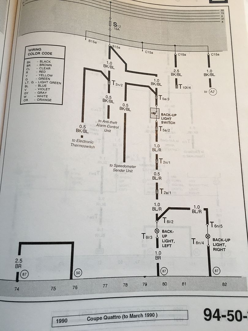
The 3 pin is for the speedometer sender unit
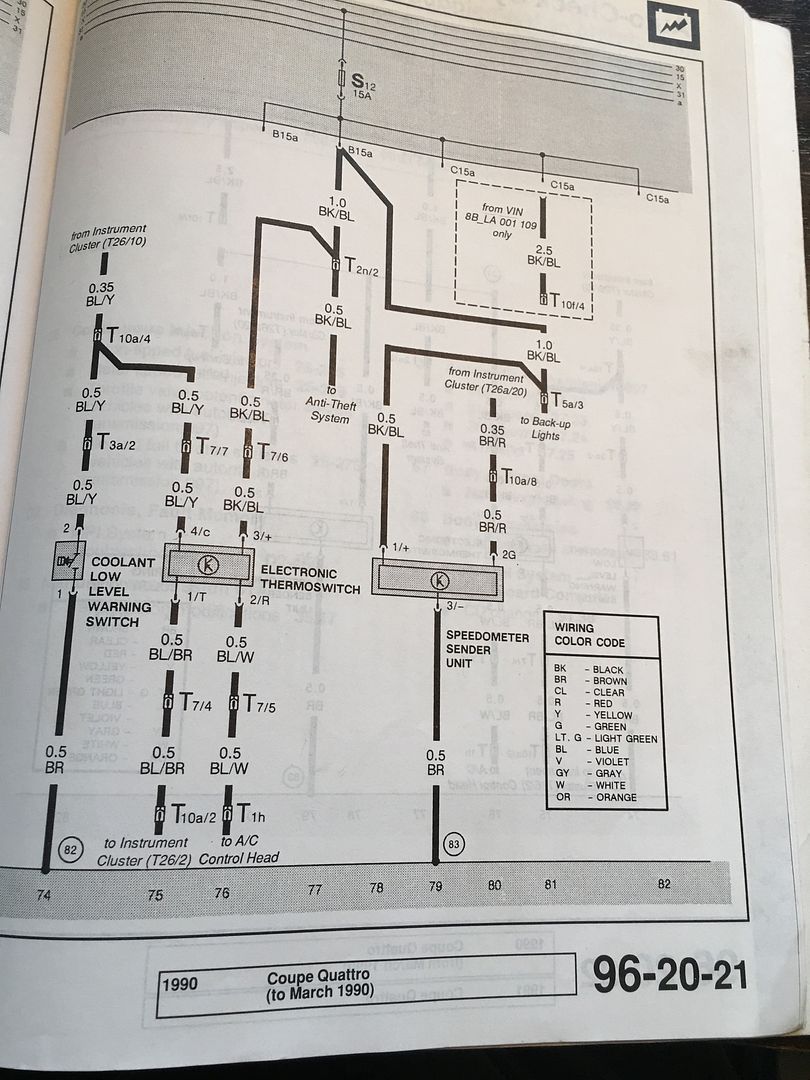
Both attach on the transmission
Re: 7A harness dissection, VEMS prep
Posted: Wed Mar 23, 2016 5:39 pm
by nmerrill
Sweet, thanks!

None of my internet scavenged diagrams went that far...
Just more crap to ELIMINATE!

Now, anyone have a comment on my noob grounding questions above?
And while I'm at it, should the actual ground wires for sensors and power loads be separated in their own looms? Obviously, this is not the case in OE looms. I don't think so, from what I understand so far. Am I correct thinking the only thing that is really different for VEMS is the method of grounding (with single common ground point etc.), but everything else can be left alone, all in the same loom?
Thanks
N
Re: 7A harness dissection, VEMS prep
Posted: Wed Mar 23, 2016 5:50 pm
by nmerrill
P.S. Grillage,
could I bother you to confirm that the after-run fan is a two prong (independent contacts, not an amp plug) with a brown green and a brown?
Re: 7A harness dissection, VEMS prep
Posted: Wed Mar 23, 2016 6:00 pm
by Grillage
That looks correct!
Also, I think I grounded my VEMS stuff direct to the battery via a large wire. not sure that's necessary though (edit - I didnt ground the VEMS ground sensor to the battery - the ECU is grounded to the battery)
Re: 7A harness dissection, VEMS prep
Posted: Thu Mar 24, 2016 9:23 am
by nmerrill
Thanks again Grillage.
So, from a (the?) wiki, in the "obsolete old version", the text reads: (emphasis added)
>>>Common Ground
The engine block is the best point from many perspectives. But it is of some importance to keep this ground point away from the alternator and starter ground paths, you can do this but adding extra grounding wire at the alternator to ensure a path of low resistance.
Having the ground path for the alternator, starter and the ecu at the same point is not a good idea. So keep the ECU connection to the block as far away as possible.
If the alternator is bolted to the engine block you way want to ground the ECU to the head
If the alternator is bolted to the cylinder head you may want to ground the ECU through the engine block, well away from the ground strap.
On engines like those fitted to some Audis (Where the alternator is bolted to the head) it is acceptable to bolt the ECU earth to the far side of the cylinder head.
....
Grounding directly at the battery is not a good idea, at the negative of the battery you always see the current pulsations from the alternator and starter, the big currents flow from battery to starter and alternator to battery, although you may hope that the battery may act as a buffer, lead batteries are pretty slow and it doesn't filter the noise very well.
The placement of the battery also change a lot of things, if you have a battery located in the boot you could need upto five 4m wires. Also And the connection at battery connectors is often forgotten by techs, are subject to aggressive corrosion, abused when connecting jump leads.
Connecting to the chassis is often a bad idea, the body of the car is an inferno of ground currents. For example the wipers, electric seats (consuming 50A+ when operated) etc may be grounded at the same point as the ECU. And voltage fluctuations are are higher as you get further from the battery. <<<<
So, from the obsolete text, it sounds like running a large wire from "common ground" junction to the block/head is the way to go.
Why this was not kept in the newer manual is open for discussion.
Perhaps because it's not important?
Re: 7A harness dissection, VEMS prep
Posted: Thu Mar 24, 2016 9:38 am
by Grillage
Maybe I didn't use the battery, I can't remember. I know I ran a ground to the front of the car for something (my battery is in the trunk now). I'll see what it was.
I'll see what I did for the common ground too.
Re: 7A harness dissection, VEMS prep
Posted: Fri Mar 25, 2016 10:00 am
by audifreakjim
Yes, ground it to the head as far from the alternator and starter as possible.
Re: 7A harness dissection, VEMS prep
Posted: Fri Mar 25, 2016 6:38 pm
by nmerrill
Thanks
So, VEMS only uses 3 wires for the Throttle POT, meaning no Throttle "switch" correct?
Throttle closed/WOT are calibrated for the ECU, but there is no separate WOT/closed signal?
Do I understand that correctly - before I yank more wires out!
Re: 7A harness dissection, VEMS prep
Posted: Sun Mar 27, 2016 7:22 pm
by Grillage
Correct. No closed throttle signal needed
Re: 7A harness dissection, VEMS prep
Posted: Tue Apr 05, 2016 10:10 am
by nmerrill
Digging a little more.
I've got my new VEMS unit, which of course, has me looking for more answers...
In no particular order:
WBO2 does not require a shielded coax cable as used in the typical narrowB harness, correct? I can pull that, and replace it with two regular wires to get the 4 needed for WB?
Knock wiring... The shielded wires in the 7A harness terminate at the ECU with two wires - yellow for one, white for the other, each with a corresponding brown wire;
The browns are treated as sensor grounds, correct?
Using a dizzy hall as only trigger (wired as secondary, and configured in ecu as primary)
The distributor Hall plug on the 7A harness has three wires; Is this correct?
Gr/W = signal -ec36 - 13
Br/W = ground - to "sensor" ground connection
Rd/Bk = +5V - ec36 - 28
Coil wiring, for 7A type coil; The existing Br/rd from the T3 connector on the 7A harness goes to ground at the intake mani, and I'm assuming it can stay there?
The AAN idle valve is a "stepper" type, correct?
What is the preferred connection to the ECU to control this?
Getting a tach signal from VEMS; Manual indicates that ec36 -4 (p259 ch. 0) is "standard" output for tach. Will this directly drive an "old school" tach like that found in the '91 vanagon?
Fuel pump:
Ec36-15 is indicated as "fuel relay". Am I correct that this would be used to switch pin 86 of the fuel pump relay, and that relay must have a diode to control voltage spikes (flyback)
Guess that's all i have for now...
Thanks in advance for any help!
Nat
Re: 7A harness dissection, VEMS prep
Posted: Tue Apr 05, 2016 5:12 pm
by Grillage
I used the switched power lead for the 12v on the Idle valve (mine is an ABZ idle valve but I believe they should work the same) and used a stepper from EC18-4 to pulse the ground to activate it.
I wired my Wideband without any shielding. it works
I wired my knocks:
PIN 1 - Signal to ECU via EC18-1 and EC18-2
PIN 2 - Ground from ECU - to sensor ground EC36-26
PIN 3 - Ground to chassis - to sensor ground EC36-26
However, I have never used them. I believe I got confirmation from Marc at EFI Express that this was correct wiring though
Your Cam position sensor wiring is what I did too.
I think that the tach should be good using EC36-4 as an output. My tach was screwy and I was getting a readout for RPM on the VEMS display but nothing on the physical gauge in the cluster so as part of trying to troubleshoot it I changed it to a stepper output using EC18-11 (stepper D). It didn't work at first but when I changed clusters to see if that was the issue it works that way. I am using a 1990 vintage Coupe Quattro cluster and I can confirm the Stepper output works on that - I would bet the original configuration would have worked too if my cluster hadn't been bad.
Re: 7A harness dissection, VEMS prep
Posted: Tue Apr 05, 2016 5:14 pm
by Grillage
Oh, I also confirmed where I grounded my sensor ground. It's on the Passenger's side rear head of the V8 - not back to the battery.
I ran a ground direct to the battery for the ECU itself
Re: 7A harness dissection, VEMS prep
Posted: Fri Apr 08, 2016 8:10 am
by nmerrill
Grillage, thanks for the details!
Spoke to Marc and got the skinny of the rest.
Time to complete the harness!


